Video: Watch this demo
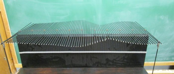
Description: A rod is suspended by two spring scales. By varying the location of the spring scales you can view the weight distribution in each scale.
Additional masses can be added to show loading and how this alters the weight distribution.
Equipment:
- Metal Rod with many holes
- 2 Sets of weights
- 2 Spring scales
- 2 Table clamps
- 2 S clamps
- 2 Long rods
- 2 Short rods
Setup Procedure:
- Setup the rods and clamps as shown in the picture. Make sure the top rods are at the same height.
- Zero the spring scales and attach one to each horizontal rod.
- Include the two sets of weights and the multi hole rod.
Demonstration Procedure:
- You may start off by suspending the rod by both ends. The scales should read the same value (top picture).
- Alter the location of the spring scales to view different weight distributions (Ex: bottom two pictures).
- You may also add additional weights to show loading of the beam.
- Explain how torque is used to describe this demonstration.
22-B2